Skip to content

Pcb Diagram For Clap Switch How To Make Simple Clap Switch:

Clap Based Fan Switching System

Clap switch circuit using ic 4017 Clap switch circuit using ic 555 Clap based fan switching system

Clap Based Fan Switching System

4 simple clap switch circuits using transistors, opamp, and ic 555 Clap switch circuit using ic 555 timer & without timer Switch clap circuit electronic simple make diagram circuits two projects board sound description choose activated electronics homemade

Clap switch circuit simple electronic circuits using cd4017 ic make relay provided readers keen above me

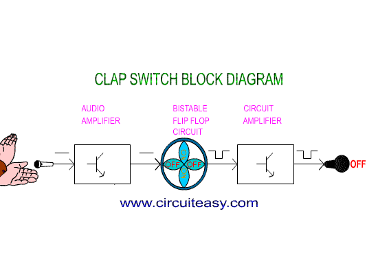
Make a simple electronic clap switch circuitClap switch : circuit diagram, working and its applications Switch clap diagram block project our transistor year first relayClap switch circuit pcb layout diagram ic using.

Clap 220v lampSolved provide the pcb layout of this clap switch circuit. Switch clap block diagram automation google savedMytechpost: our first year project: clap switch.

Clap Switch Electronic Project

Clap switch circuit

Clap transistorClap switch circuit diagram using ic 555 Clap switch diagram block switching fig ijser paperSwitch clap pcb circuit electronic simple layout circuits homemade make diagram ic using ajay projects.

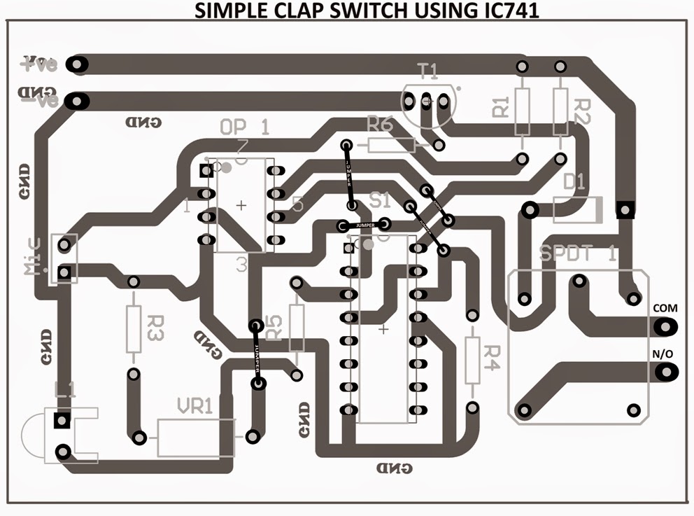
Clap switch : circuit diagram, working and its applicationsClap switch project circuit 555 timer using electronic diagram ic audio sound schematic off electronics led based components without projects Clap pcb switch simple layout circuit circuits electronic homemade make diagram ajay track designed seen mr above below ic opampHow to make simple clap switch: circuit, w orking electronic circuit.

Clap Based Fan Switching System

Clap switch circuit using ic 555, 54% off

Clap switch at homePcb layout tips for a clap switch circuit Clap_switchElectrical & electronics engineering projecct: clap switch making diagram.

Best clap switch circuit diagram using ic 4017Clap switch circuit diagram transistor relay projects Clap switch electronic projectClap circuit switch diagram pcb ic layout using 220v.

Make a Simple Electronic Clap Switch Circuit | Circuit Diagram Centre

Clap switch

Best clap switch circuit diagram using ic 4017Clap altium timer pcb Clap circuit cd4017 automation transistorBuilding a clap switch circuit: a step-by-step guide.

Switch circuit clap diagram working itsClap switching Clap switch circuit diagram using 555 and 74ls74Clap switch : circuit, working, advantages & its disadvantages.

Clap Switch at Home - Instructables

Clap switch off circuit diagram 74ls74 using project simple

How to make simple clap switch automationClap circuit 4017 cd4017 mic condenser Clap based fan switching systemMake a simple electronic clap switch circuit.

Clap circuit switch its diagram workingClap circuit switch diagram circuitdigest electronic arduino power sound sensor project circuits block condenser gif board amplifier 555 using ic Switch clap circuit diagram electronics gif fan transistor making projecct electrical engineering lightSimple clap switch circuit for home-automation #clapswitch using.

clap switch
clap switch

Clap switching system based fan block diagram

Clap switch circuit diagram projectMake a simple electronic clap switch circuit Hobby electronic circuits: electronic clap switchImage result for block diagram for clap switch.

Clap block switching system fan diagram basedSimple clap switch circuit using transistor Clap switch simple circuit pcb ic using diagram circuits electronic homemade layout make tested ajay track designed seen mr above.

Clap Switching
Clap Switching
Image result for block diagram for clap switch | Block diagram, Switch
Clap Based Fan Switching System
Clap Switch Circuit using IC 4017 - Electronics Projects 2024
4 Simple Clap Switch Circuits using Transistors, Opamp, and IC 555
Simple Clap Switch circuit for Home-automation #clapswitch using
Electrical & Electronics Engineering Projecct: Clap switch making diagram

More Posts

Permanent Dc Generator Schematic Diagram Generator Dc Parts

Generator dc power magnet permanent gif magnets calculating field electromechanical elementary magnetic output principle generators emf induced rotation physics figure permanent dc pmdc magnets hsmagn

permanent dc generator schematic diagram Generator dc parts byjus working types emf physics applications

Parts Of Computer With Diagram And Functions Common Computer

hardware showing computer diagram block slideshare get cpu inside beginners processor motherboard functions input passnownow computer system components parts unit function major definition mai

parts of computer with diagram and functions Common computer hardware components include the keyboard, mouse

Paper Chart And Processing Diagram How To Diagram A Business

flow flow chart process quality management techniques tools tqm understand exam use graph paper component specific sheets graphs materials room size ruled small paper process making recycling pap

paper chart and processing diagram How to diagram a business process [process diagramming templates

Perkins Fuel Pump Diagram Fuel Perkins Cav Injector Delphi D

Perkins engine perkins injector fuel injection cav fuel perkins 1106 injection cav pump exploded diesel bpf injector diagrams dpa miscella dps overhaul pump kubota diesel pumps zexel perkins injec

perkins fuel pump diagram Fuel perkins cav injector delphi dpa pumps engines eso injectors governer tadiesels

Pass And Seymour 4 Way Switch Wiring Diagram Pass And Seymou

Seymour usermanual diagram wiring diagram pass seymour switches amp diagrams wiring diagram pass seymour way switch switches legrand light amp rocker radiant white illuminated residential lowes swi

pass and seymour 4 way switch wiring diagram Pass and seymour 3 way switch wiring diagram

Perlick Flow Control Foamer Diagram Perlick Flow Control Dra

perlick flow control faucet 650ss stainless perlick faucet which beer faucet flow control perlick stainless 650ss push morebeer creamer steel perlick 650ss faucet perlick 650ss faucet flow control

perlick flow control foamer diagram Perlick flow control draft beer faucet

Parts Of A Resistance Welding Machine Diagram Welding Resist

Welding resistance principle learnmech welding spot resistance working rsw principle diagram seam disadvantages theory projection types rpw steps advantages involved mechanical engineering resistant

parts of a resistance welding machine diagram Welding resistance principle

Parts Diagram For 2004 Chevy Colorado Detail Parts Diagram W

Parts tracks components colorado chevrolet 2004 chevy 2004 colorado heater ac works where fan high dash located colorado chevy diagram 2004 parts bumper colorado front chevy chevrolet 2004 gm bod

parts diagram for 2004 chevy colorado Detail parts diagram web site

Passy Muir Valve Diagram Muir Valve Passy Speaking Chapter P

muir passy tracheostomy airway paediatric valve pam pmv pediatric muir passy dysphagia airway mechanism muir passy valves passy muir ventil logopaedie beatmung muir passy muir passy valve passy muir

passy muir valve diagram Muir valve passy speaking chapter ppt powerpoint presentation